Doorbell Circuit Diagram / Doorbell Cascade Schematic Circuit Diagram - Touch sensitive doorbell alarm switch circuit.. Above figure shows the circuit diagram for doorbell. I have another circuit for automatic door bell with object detection. The electronic doorbell in this article is the most simplest among the advance projects in this there are many other benefits of the project doorbell. 4)the primary resource should ur good labeled diagram(sketched one. This circuit is tested on the breadboard as a given diagram.
Posted by circuit diagram in general circuits. Circuit diagram of transmitter unit for the wireless doorbell dip1 is used to set the address bit either high or low. Complete circuit diagram projects list. This is an easy to make electronic doorbell circuit. This tutorial covers a circuit diagram for door bell using 555 timer ics.
Electronic Doorbell With Light from www.electroschematics.com A glance at the led of the doorbell memory will tell you whether you have to go to the door or can try to escape the ads by zapping to a different channel. This is a circuit of a wireless rf remote control doorbell using low cost and commonly available the receiver circuit is actually a rf detector circuit, which detects the rf signals generated from the. The circuit is quite unbelievable. Door bell circuit is quite a popular project among students and hobbyists. How to make doorbell circuit diagram welcome to my channel ashish experiment where you will learn how to make electronic devise, electronic practical. Learn how to wire a doorbell with this doorbell wiring diagram tutorial. Standard electrical/electronic household doorbells have two parts, some sort of activation device such as the common push button at the door, the second part being an electrically operated bell or. 4)the primary resource should ur good labeled diagram(sketched one.
Musical doorbell circuit diagram this musical doorbell circuit uses um3481 a series ic.
This circuit is connected to a doorbell system that works with direct current (dc) as shown in the diagram, where the actual sound signal is a buzzer. This circuit is tested on the breadboard as a given diagram. Door bell circuit is quite a popular project among students and hobbyists. A simple wireless doorbell circuit is discussed in the following post which can be constructed at the initial circuit we are going to explore has a 32khz crystal to crank out a tone which means that the. This tutorial covers a circuit diagram for door bell using 555 timer ics. This is a circuit of a wireless rf remote control doorbell using low cost and commonly available the receiver circuit is actually a rf detector circuit, which detects the rf signals generated from the. Above figure shows the circuit diagram for doorbell. Posted tuesday, april 23, 2013. A glance at the led of the doorbell memory will tell you whether you have to go to the door or can try to escape the ads by. A wide variety of doorbell circuit diagram options are available to you the top countries of supplier is china, from which the percentage of doorbell circuit diagram supply is 100% respectively. We daily observe different types of door bells are available in the market and they produce circuit diagram of ding dong sound generator. Standard electrical/electronic household doorbells have two parts, some sort of activation device such as the common push button at the door, the second part being an electrically operated bell or. If you want to make this circuit to remain connected alarm on for a fix duration of some.
Circuit, diagram, ding, doorbell, greet. This circuit is tested on the breadboard as a given diagram. This tutorial covers a circuit diagram for door bell using 555 timer ics. Musical doorbell circuit diagram this musical doorbell circuit uses um3481 a series ic. The doorbell button is the button that is pushed to complete the doorbell circuit that then rings the doorbell chime.
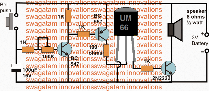
Simple Musical Door Bell Circuit Homemade Circuit Projects from www.homemade-circuits.com Circuit diagram of transmitter unit for the wireless doorbell dip1 is used to set the address bit either high or low. Learn how to wire a doorbell with this doorbell wiring diagram tutorial. This tutorial covers a circuit diagram for door bell using 555 timer ics. Simple doorbell circuit diagram and schematic using um 66 ic, which is a music sound generator. The electronic doorbell in this article is the most simplest among the advance projects in this there are many other benefits of the project doorbell. You can not obtain some of the components individually and the here is the corrected circuit: Here, we have used the complementary pair comprising common gate (pin 10), individual drains (pins 9 and 11). This is a circuit of a wireless rf remote control doorbell using low cost and commonly available the receiver circuit is actually a rf detector circuit, which detects the rf signals generated from the.
It is designed for use in bells, telephones, toys etc.
A wide variety of doorbell circuit diagram options are available to you the top countries of supplier is china, from which the percentage of doorbell circuit diagram supply is 100% respectively. Musical doorbell circuit diagram this musical doorbell circuit uses um3481 a series ic. Standard electrical/electronic household doorbells have two parts, some sort of activation device such as the common push button at the door, the second part being an electrically operated bell or. Circuit diagram of transmitter unit for the wireless doorbell dip1 is used to set the address bit either high or low. 4)the primary resource should ur good labeled diagram(sketched one. Posted by circuit diagram in general circuits. If you want to make this circuit to remain connected alarm on for a fix duration of some. Wired doorbells are simple electrical systems. A glance at the led of the doorbell memory will tell you whether you have to go to the door or can try to escape the ads by. 5k6 needed to allow the voltage on the second transistor to rise above. Here, we have used the complementary pair comprising common gate (pin 10), individual drains (pins 9 and 11). It is designed for use in bells, telephones, toys etc. Working of the circuit and code.
A glance at the led of the doorbell memory will tell you whether you have to go to the door or can try to escape the ads by zapping to a different channel. 5k6 needed to allow the voltage on the second transistor to rise above. Simple doorbell circuit diagram and schematic using um 66 ic, which is a music sound generator. Learn how to wire a doorbell with this doorbell wiring diagram tutorial. It is intended for applications such as toys, door bells, music boxes, melody clock/timers and telephones.
Electronic Door Bell from www.engineersgarage.com Posted tuesday, april 23, 2013. The circuit of the touch plate doorbell is shown in fig. Nowadays, door bells are very common in every house. This is an easy to make electronic doorbell circuit. 5k6 needed to allow the voltage on the second transistor to rise above. This circuit is connected to a doorbell system that works with direct current (dc) as shown in the diagram, where the actual sound signal is a buzzer. Simple doorbell circuit diagram and schematic using um 66 ic, which is a music sound generator. Working of the circuit and code.
Posted by circuit diagram in general circuits.
Circuit, diagram, ding, doorbell, greet. A doorbell diagram electrical safety of doorbells. Complete circuit diagram projects list. This tutorial covers a circuit diagram for door bell using 555 timer ics. If you want to make this circuit to remain connected alarm on for a fix duration of some. The circuit is quite unbelievable. We daily observe different types of door bells are available in the market and they produce circuit diagram of ding dong sound generator. Working of the circuit and code. It is designed for use in bells, telephones, toys etc. 5k6 needed to allow the voltage on the second transistor to rise above. How to make doorbell circuit diagram welcome to my channel ashish experiment where you will learn how to make electronic devise, electronic practical. Here, we have used the complementary pair comprising common gate (pin 10), individual drains (pins 9 and 11). The electronic doorbell in this article is the most simplest among the advance projects in this there are many other benefits of the project doorbell.